2019年12月31日星期二

3 Phase Induction Motor Construction You Should Know

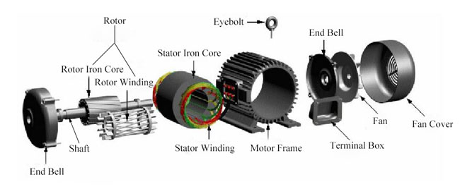
Induction motor, also known as asynchronous motor, is a kind of AC electric motor. According to the different power phase, it can be divided into single-phase and three-phase motor. The main construction of induction motor is composed of two parts - stator and rotor. In addition, there are end bells, bearings, motor frame and other components. The following will give more details about the main structure of three-phase induction motor or asynchronous motor.

induction motor construction

1. Stator
Stator is a fixed part of induction motor, consisting of stator iron core, stator windings andmotor frame.

Stator iron core
As a part of the motor magnetic circuit, it is installed inside the motor frame. It is a hollow cylinder, outer wall of which is connected to the motor frame. And the stator windings are placed in the slot of the iron core inside. In order to reduce the loss of iron core, the stator iron core is stacked up with 0.5 mm thick silicon steel sheets.

Stator winding
It is a part of the motor electric circuit, generating the rotating magnetic field by inducing three-phase alternating current. Stator windings are wound with insulated copper wires and embedded in the stator slot, which are separated by insulating material between the windings and the slot.

Motor frame
It fixes the stator core and stator windings and supports the rotor with two end bells. Meanwhile, it protects the electromagnet part of the entire motor and dissipates the heat generated during motor operation. The frame is typically made from iron or aluminum.


2. Rotor
Rotor is a rotating part of induction motor, including iron core, windings and shaft etc.

Rotor iron core
It is also a part of the magnetic circuit, generally stacked by silicon steels and fixed on the shaft.

Shaft
It plays a role of converting torque and support the rotor. It is generally made of medium carbon steel or alloy steel.

Rotor winding
It produces induced current as cutting the stator magnetic field, and under the effect of the rotating magnetic field, it forces the rotor to rotate. According to the different structure, it can be divided into two types: squirrel-cage rotor and wound rotor.
The wound-type rotor windings can be connected into star or delta connection. In general, the small capacity rotor is connected into delta while the large and medium capacity one is connected into star. These three windings wire ends are connected to three slip rings fixed on the shaft by a set of electric brush. It can connect the external resistor to the rotor winding circuit. The purpose of string resistance is to improve the motor characteristics or adjust the rotate speed.
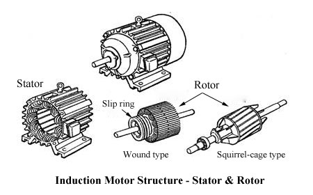
Induction motor structure stator and rotor


https://stepper011.jimdofree.com/2019/11/08/what-stepping-modes-does-a-stepping-motor-have/
https://c00alvin.blogrip.com/2019/11/07/how-do-you-control-and-run-a-stepper-motor/

Industrial Applications of Brushless DC Motors

Industrial Applications
For industrial applications, brushless DC motors are primarily used in servo, actuation, positioning, and variable speed applications where precise motion control and stable operation are critical for the satisfactory operation of the manufacturing or industrial process. They are commonly used as:

Linear motors
Servomotors
Actuators for industrial robots
Extruder drive motors
Feed drives for CNC machine tools


Linear Motors
Linear motors produce linear motion6 without the need of a transmission system, such as a ball-and-lead screw, rack-and-pinion, cam, gears or belts, that would be necessary for rotary motors. Transmission systems are known to introduce less responsiveness and reduced accuracy. Direct-drive linear motors do not exhibit these shortcomings.

Servomotors
Servomotors are used for mechanical displacement, positioning or precision motion control based upon an input control and output feedback signal that establishes a tightly controlled, stable, closed loop operation. Servomotor drives are commonly used in machine tool servos, robotic actuator drives, among others.


Actuators for industrial robots

Permanent magnet DC motors12 primarily function as the actuators to move the joints of industrial robots for pick-and-place or tool positioning in assembly, welding and painting operations. (It merits noting that when heavy payloads are involved, hydraulic motors are typically used.13) BLDC motors are preferred over brushed motors in robotic applications due to their compact size, power density, and maintenance-free characteristics.

Extruder drive motors

The function of the extruder drive & motor is to provide energy to turn the screw that compresses the polymer. 14 DC drives are the most popular extruder drive due to their low cost and versatility. Since variations in screw speed can change the dimensions of the final extruded product, a precision motion control system is required to ensure product quality.

Feed drives for CNC machine tools
There are two drives used in CNC machine tools: spindle and feed drives.17 Spindle drives provide the motion and power for drilling, milling or grinding operation while feed drives function as axis drive motors and essentially replace the “manual hand wheel controls used in conventional machine tools.

Source:https://www.oyostepper.com/article-1108-Industrial-Applications-of-Brushless-DC-Motors.html


http://stepper011.simplesite.com/444096647
http://uid.me/christ_cecillia1